Working with the Document Setup - New OMR File Wizard
Select New OMR File from the Getting Started Options dialog to start the Document Setup wizard. This is a series of dialogs that prompts you for information about the document. Set options on each wizard dialog, then click Next. At any time during document setup you can click Finish to build the document; the defaults are used for the remaining options.
- Scanner Options:
- OpScan-NSIGHT 4, 4ES, 4U
- Pencil read head
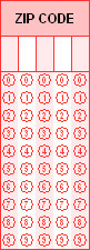
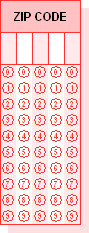
- Response Options:
- Oval response type
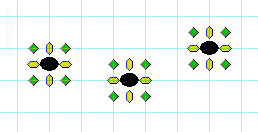
- 6x6 grid
- Color Options: Black, White (opaque), and 28 Carnival (red) colors
- Page Size Options: US Letter, Portrait, 8.5 x 11 inch
- Paper Options:
- Single-part structure
- Single sided
- Cut sheet format
The dialogs not mentioned above (continuous, multi-part, marginal words, booklet options) appear only if you make certain choices on the Paper Options dialog. Those defaults are discussed with the dialogs, below.
What's on the Screen?
The document setup wizard includes the following steps:
-
 Set Scanner Options
This step specifies the type of scanner you plan to use to scan forms.
Use this element… …to… Brand
Select a Scantron scanner family. Different scanners have different form requirements. Selecting the scanner family and model determines the choices available for the other elements of this dialog.
Model
Select the model of your scanner. The selection box only displays the models for the scanner family you selected under the Brand option.
TIP: If you are designing a document that will be used on a variety of models or you don't know what model you have, select the General Scanner Family option.
Read Type
Select the read head type of the scanner for which you are designing the document. This is where the possible dropout colors are determined for the document. There are two options:
- Ink: A scanning system designed to process forms marked with a blue or black ink pen, typically a ball point pen. Felt tip pens as usually discouraged as the ink may soak through the paper. Ink read scanners can also read black lead pencil marks.
- Pencil: A scanning system designed to process forms marked with a pencil, typically a Number 2 black lead pencil.
TIP: Due to the use of a different light source (white versus red or infrared), the iNSIGHT 20/20 Plus and iNSIGHT 30 scanners use a different set of form colors than other Scantron scanners. See Color Options for Data Collection Forms or Appendix A of the appropriate scanner's Operator's Guide or the appropriate color book (if available) for a list of form colors approved for use with these scanners.
-
Set Response Options
This step specifies the type of response grids you want to use as the default for the document. The selections available are based on the scanner model selected in the Document Setup, Scanner Options dialog. The scanner and read head type you selected are listed for your reference.
Use this element… …to… Response Style
Select the response position shape you want for your document. This can be ovals or circles.
Only the types supported by your scanner model and read type selection are available. Each response type has its advantages. For example, circles are easier to fill in than ovals, but ovals take less room. If you are not sure which is best for your application, contact Scantron Technical Support.
NOTE: In some cases, OMR response shapes may not appear to be smoothly shaped circles or ovals. Accurate rendering of these shapes on your monitor depends on your operating system, your display settings, the zoom percentage you have selected, and other factors. Printed OMR response shapes will be smoothly rendered.
Grid
Select the response grid spacing for the response positions on your document. Circle responses support 6x5 and 6x6 grids while oval responses support 6x5, 6x6, and 6x8 grids.
The selection is based on the scanner, read head type, and response style you selected in previous document setup options. The grid spacing dimension is based on the number of response positions in one square inch. The first number is the read head (horizontal) spacing and the second is the timing mark (vertical) spacing.
The grid spacing you choose depends on the space you have on your form and the audience using the form. For example, senior citizens may have trouble seeing the smaller bubbles in a 6x8 grid, so with that particular audience you might decide to use a 6x5 grid. When you select a grid option you can see a sample of the grid on the left side of the dialog.
The grid spacing you select determines the background grid lines that will be displayed in your document background workspace if you have selected Grid Lines in the View Menu. These are also the dimensions that will be used as the base for the Snap to Grid feature.
-
Set Color Options
This step specifies the colors you want to be able to use in the document. The selections available are based on the scanner model selected in the Document Setup, Scanner Options dialog. The scanner and read head type you selected are listed for your reference.
Use this element… …to… Selected Colors
Specify the colors available for document design.
When you first enter this dialog, the colors listed are black, white (opaque), and a dropout color appropriate for the scanner model you selected in Document Setup Scanner Options dialog. To add more colors to this list click Change.
When you exit this dialog, the colors listed here are what will be available for use in the document. Black and white colors are required. You can have a maximum of seven colors (including black and white) for single-sided documents; nine colors (including black and white) for double-sided documents.
Change
Add and delete colors available for use with your document. You cannot delete black and white.
CAUTION: Some colors are marked as discontinued in the Change Colors dialog. They are no longer supported by Scantron Print Services but are still listed in DesignExpert software so that you can open a file created in an earlier version of the software and identify where a color change may be required.
TIP: Due to the use of a different light source (white versus red or infrared), the iNSIGHT 20/20 Plus and iNSIGHT 30 scanners use a different set of form colors than other Scantron scanners. See Color Options for Data Collection Forms or Appendix A of the appropriate scanner's Operator's Guide or the appropriate color book (if available) for a list of form colors approved for use with these scanners.
For the iNSIGHT 20/20 Plus and iNSIGHT30:
Select the primary dropout color from the Drop-Out Colors and Highlight Colors list. The list automatically adjusts to display the second colors that are available. You can then select the second color, and the list adjusts to display the third colors that are available. -
Set Page Size Options
This step specifies the page size and orientation of your document.
Use this element… …to… Standard Sizes
Select the page size for the form you are designing.
The physical size displays in the Page Size area. If you do not see a standard size that meets your needs, select Custom and enter the dimensions in the Page Size text area.
Page Size
View the page dimensions for the size selected in the Standard Size selection box.
OR
Enter the desired page size dimensions of your customer page size in this area.Change the units used to define the page size by scrolling through the units of measure and choosing one. The software automatically converts the dimensions to reflect the selected unit of measure.
NOTE: You cannot create a Custom size that is larger or smaller than the maximum or minimum page size allowed by the scanner you have selected.
-
Set Paper Options
This step specifies the paper type and printing format for the form. Choices you make here affect the remaining wizard dialogs you will see.
Use this element… …to… Single-Part, Multi-Part, or Booklet
Choose the physical structure you want to use in your form:
-
Single-Part
A flat single sheet of paper.
-
Multi-Part
Used to capture the same “marked” data onto multiple copies of the same form, with the top sheet used as the scannable document. These form sets can be produced as either snapsets (cut sheet set) or as continuous sets. They can also be produced as either carbon inter-leaf sets or NCR (no carbon required) sets.
-
Booklet
A set of cut sheet forms collated in a specific sequence. Stitched booklets have one or two staples in the fold of the signature, holding the pages together. Glued booklets are trimmed at all folds, then the spine is clamped and glued together. Usually booklets also include perforations, to remove the individual sheets for scanning.
If you need more detail about these structures, contact Scantron Technical Support.
When you choose Multi-Part or Booklet, the subsequent Document Setup dialogs change to reflect the additional options available for the selected structure. Also, if you choose Booklet, you cannot choose the Single Sided, Double Sided, or Continuous options.
NOTE:Scantron DesignExpert software does not support merge printing, including pre-printing, pre-slugging, and bar coding, for multi-part forms or finished booklets. Merge printing can, in some cases, be performed with booklet pages before the booklet is bound.
Single Sided or Double Sided
Choose Single Sided if you want to print on only one side of the form. Choose Double Sided if you want to print on both sides of the form.
Cut Sheet or Continuous Form
Choose Cut Sheet if the document page(s) are not attached to each other. Choose continuous form if you are planning to use a tractor feed to feed your forms through a line printer.
NOTE:Scantron DesignExpert software does not support merge printing, including pre-printing, pre-slugging, and bar coding, for continuous forms.
-
-
Set Additional Paper Options
Depending on what you selected in Step 5, you may also see the following steps.
If you selected Multi-Part in Step 5 If you selected Booklet in Step 5 Set Multi-Part Options
This step specifies the options needed to develop multi-part forms.The dialog appears only if you selected Multi-Part on the Paper Options dialog.
Use this element… …to… Number of Parts
Select the total number of parts in your form, up to six.
Contact your Scantron Print Services Customer Service Representative for information on designing multi-part forms with more than six parts.
Glue Pos
Set the location on the form where the glue binding will be. The squares correspond to the top, bottom, left, and right positions. This option is only enabled if you select Cut Sheet in the previous step.
Crimp Pos
Set the location of the form where the crimp binding will be. This option is only enabled if you selected Continuous in the previous step.
Crimping a form is typically used in continuous multi-part forms where a strong binding is not needed. The squares correspond to the top, bottom, left, and right positions.
Design Color by Part
Define the colors available for each part of the form.
- Select a Part other than 1.
- Check Same Color as Part 1 set the specified part to use the same colors as Part 1. Clear this box to specify different colors for this part.
- (If you cleared the checkbox) Select the color for the selected part.
- Repeat these steps for each part.
Set Booklet Options
This step specifies the length of the booklet and type of binding used on the pages.The dialog appears only if you selected Booklet on the Paper Options dialog.
Use this element… …to… 4-Page Folder
Specify that the form does not require a binding type but uses a 17" x 11" sheet folded in half to form 4 pages.
8-Page Glued Booklet
Specify that the form uses 4 sheets (8 pages) bound at the spine with glue. An eight-page glued booklet can have a Litho-code on all four scannable sheets.
8 or More Pages
Specify that the booklet should have stitched (or stapled) binding and 8 or more pages.
Use the arrows in the scroll box to select the number of pages you want. You are limited to increments of 4 pages. The eight-page stitched booklet can only have a Litho-code on two of the four scannable sheets. Other than this, the main difference between the 8-page choices is the aesthetic impact of a glued booklet versus a stitched one.
If you need more than 120 pages in the booklet, contact your Scantron Print Services Customer Service Representative for more information on how to design your form.
NOTE: Scantron DesignExpert software does not support merge printing, including pre-printing, pre-slugging, and bar coding, for finished booklets. Merge printing can, in some cases, be performed with booklet pages before the booklet is bound.
Set Marginal Words Options
This step specifies how the marginal words appear on your multi-part form. Marginal words appear in the form margins, and generally provide identification for each form part (e.g., "Original", "Human Resources Copy", "Employee Copy"). You can specify different marginal words for each part. The dialog appears only if you selected Multi-Part on the Paper Options dialog.
Use this element… …to… Text and Color by Part
Define the text content and color for the marginal words.
- Select a part.
- Type the text you want printed in the margin.
- Choose a color for the text.
- Repeat these steps for each part.
This list comes from the list of colors for the part you selected in the previous wizard dialog.
Position
Set the location for the margin text.
- Select a part
- Select a position.
- Repeat these steps for each part.
The position buttons are oriented in relation to the form shown in the illustration in this dialog. That is, when the illustration shows the binding at the top, then selecting the top left position button causes the word to print in the top left edge of the form.
If you select one of the two middle positions, the words will print along the margin, or sideways when compared to how they would print if you had selected another position.
Change Font
Set the font attributes for the margin text. Each part's margin text can have different font attributes.
- Select a part.
- Click Change Font…
- Choose a font, size, and attributes. See Font dialog for details.
- Click OK.
- Repeat these steps for each part.
Special Instructions
Add up to 300 characters of special instructions for Scantron Print Services concerning your multi-part form. Anything you enter here automatically appears in the Job Specifications sheet. See the Special Instructions dialog for details. Click Finish; if you selected Booklet, there are no further options. If you also selected Continuous in step 5, go to the next step. Set Continuous Options (only if you selected Continuous in step 5)
This step specifies select carrier strip width and location for continuous forms. This dialog appears only if you selected Continuous on the Paper Options dialog.
Use this element… …to… Carrier Strip Width
Select 1/2" or 5/8".
Carrier Strip Location
Select the strip location. The carrier strips can be located on the top and bottom, or on the left and right sides of your form.
Once you complete the Document Setup Wizard, you can start adding shapes, response grids, hand print areas, skew marks![]() Black ovals printed on a form used to provide additional integrity checking on the form's printing, dimensional stability of the paper, and transportation of the form through the scanner. If the form if printed at low precision (e.g., by a laser printer) or a feed problem that occurs during scanning skew marks prevent user marks from being mis-read. Skew marks are used to add an additional layer of data integrity checking. Skew marks appear on the edge of the paper opposite the guide edge. See Also form ID, guide edge, timing marks, and other elements to your form.
Black ovals printed on a form used to provide additional integrity checking on the form's printing, dimensional stability of the paper, and transportation of the form through the scanner. If the form if printed at low precision (e.g., by a laser printer) or a feed problem that occurs during scanning skew marks prevent user marks from being mis-read. Skew marks are used to add an additional layer of data integrity checking. Skew marks appear on the edge of the paper opposite the guide edge. See Also form ID, guide edge, timing marks, and other elements to your form.
How do I…
- Click a shape tool (
 ,
,  ,
,  , or
, or  ) on the toolbar.
 - Click the workspace and drag until the shape is the size you want.
See Tools Menu for details on drawing each type of shape.
Once the shape is drawn, you can move, resize, or adjust its properties:
Scantron DesignExpert provides two ways to set up a response grid:
- Select Tools > Grid Wizard.
- Use the Response Grid Tool:
- Do one of the following
- Select Tools > Response Grid
- Click

- Select Tools > Grid Wizard
- Place the mouse pointer where you want the grid to begin, click and drag the mouse pointer to where you want the grid to end, then release the mouse button.
Once you have created a response grid box, you can modify the response grid box settings.
- Select Tools > Hand Print or click
 .
. - Place the mouse pointer where you want the hand print to begin, click and drag the mouse pointer to where you want the area to end, then release the button.
TIP: Do not use the Hand Print tool to draw the write-in areas at the top of OMR response grids. Use the Box tool instead to draw write-in boxes that are the exact size required.
Once you have created a hand print area, you can modify its settings.
- Select Tools > Caption or click
 .
. - Place the mouse pointer where you want the caption box to begin, click and drag the mouse pointer to where you want the caption box to end, then release the button.
- Enter the desired text and click Apply and/or OK.
Once you have created a caption box, you can modify the settings. At any time, you can change the default caption text that appears.
- Select Tools > Graphic or click
 .
. - Place the mouse pointer where you want the graphic to begin, click and drag the mouse pointer to where you want the graphic to end, then release the button.
- Double-click the graphic box to display the Open dialog, then find and select the graphic file you want to import.
See Importing Graphics for details.
Once you have created a graphic box and imported a graphic, you may modify the graphic settings.
- Select Tools > Text or click
 .
. - Place the mouse pointer where you want the text box to begin, click and drag the mouse pointer to where you want the text box to end, then release. The text cursor appears immediately inside the text box, where you can enter the text characters you need, or import a text file using the Text Menu.
TIP: When you create a text box that will be placed to the left-hand side of an OMR response grid, do not locate it edge to edge with the OMR response grid. Instead, provide a space between the two shapes of at least half a response position. This design strategy will help make your form easier to use and avoid the possibility of text inadvertently overlapping OMR response bubbles.
Once you have created a text box, you can modify the text box settings. You can also modify the text appearance. At any time, you can change the default text settings.
You may want to create the illusion that an element of your design, such as a box or response grid, is floating and casting a shadow. This effect is called a "drop shadow."
|
Without
|
With
|
Scantron DesignExpert does not have a drop shadow tool but it is relatively easy for you to create your own simple drop shadow if you need one.
- Create or select an element.
- Draw a box of the same size as the element.
- Use Modify Box to create your "shadow" by changing the box Stroke and Fill to a screen percentage such as 15%.
- Duplicate this box and use Modify Box to change the second box Stroke and Fill to Solid Style and White Color.
- Drag the "white" box on top of your element (an OMR response grid in this case) then move it to the graphic layer behind the element (right-click the box, then choose Move to Back).
- Drag the 15% screened box on top of your element and offset down and to the right by half a response grid space. Then, move it to the graphic layer behind the element.
- Select all of the elements in your finished grid and Group them so that they stay together when moved on the workspace.
Your element is complete with drop shadow. We suggest you experiment with other shapes, screen percentages, and colors. And, be sure to add it to your Shape Library if you will use it with other form designs.
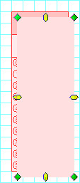
Skew marks are black ovals printed on an OMR form. Skew marks are an option that, when used on a form, provide additional integrity checking on the form's printing, dimensional stability of the paper, and transportation of the form through the scanner. With the use of skew marks on a form, if the form has a dimensional print issue, dimensional paper issue, or a feed problem that occurs during scanning with skew mark detection enabled, an error will be generated to prevent user marks from being miss-read. Skew marks are used to add an additional layer of data integrity checking.
Skew marks are only used on OMR forms. They should not be used on Image forms. Image forms employ the use of anchor marks for skew detection rather than skew marks.Although skew marks can be placed anywhere on a form, in reality they are most useful when placed near the outside edge of a form.
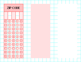
The following figure illustrates two skew marks on the top half of a form:
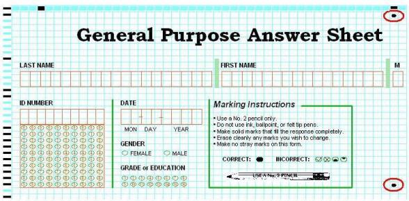
Skew marks must be placed on a line containing a timing mark. You can place any number of skew marks on a form but you typically will not need more than two or three. A typical implementation is to place one skew mark near the top of a form and a second skew mark near the bottom of the form. If you have an area on the form that you are particularly concerned about you might consider putting one or more skew marks near that data. If desired you can place skew marks on both sides of a form.
NOTE:When scanning with an iNSIGHT 20/20 Plus or 30, the recommended skew mark locations are at 1", 3.5" and 9.5" down the form, in cell 45 or higher.
- Set Zoom to 200% so it’s easier to see your work.
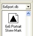
- Select the proper shape library for your form design. For example, use 6x6port.slb for a portrait format OMR form using 6x6 response spacing.
- Click and drag the skew mark to the desired location on the form.
CAUTION: Selecting the incorrect shape library will cause scanning compatibility problems.

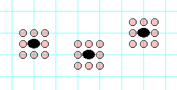
Each skew mark must be aligned with a timing mark and centered within a cell, as shown below. The skew mark is locked when placed.

If the skew mark is not centered within a cell, as shown in the examples below, you must move or replace it.

CAUTION: Skew marks are not included in the application file when you Export to ScanTools. They must be added to your ScanTools application after you have opened the file with ScanTools software.
See Working with the Shape Library for details.