Modifying Lines
Use this dialog to change settings for one or more boxes on your document. Do one of the following to access this dialog:
- Double-click the shape.
- Right-click the shape, then select Modify.
- Select the shape, then select Shape Menu > Modify.
- Select the shape, then press Ctrl+E on your keyboard.
What's on the screen?
The Modify Box dialog includes the following tabs:
-
 Stroke and Fill
Change the thickness, style, color, and screen for strokes and fills on the selected box(es).
Use this element… …to… Stroke Set the options for the stroke (line) used in this box. Settings are:
Use this setting… …to… Width
Define how wide the stroke line is. Select a unit of measurement from the drop-down list then enter a numeric value.
The unit of measurement can be set in points, millimeters, inches, or fractions of an inch (1/5, 1/6, 1/8, and 1/10). For example, if the unit of measurement is 1/10" and the width is 2.0, then the stroke line is 2/10" wide.
Style
Set the color style. Choices are:
- Solid: the stroke and fill to be visible and have the color and screen values you select
- None: the stroke and fill will not be displayed or printed; you cannot choose a color or screen. Use this choice to remove all color from a shape.
Color
Set the color. The choices are selected from the list established when you created the document, including black and white.
Screen
Set the color screen. Screens are an economical way of adding color variety using a single-color process. They also enable you to add shading without using a different color. Select a value between 10% and 100%, in 10% increments (plus 15%). The lower the value, the lighter the color appears.
TIP: If you are using shading to create an underlay, use ‘none’ as the color. Any gradient of shade, or the color white, will be screened at 50%, and appear grayed out.
Overprint Indicate whether this shape is overprint.
The default is for this box to be checked. This means that any graphic element you create will be printed on top of the element beneath it. The top element will not knock a hole in the bottom element.
CAUTION: Do Not Change this setting unless you are familiar with the complexities of color overprinting and color trapping. When you send your document to Scantron Print Services for printing, our graphic arts specialists will analyze your form and determine if the overprint setting for any element needs to be modified. If you are unfamiliar with this process, we will perform this function for you.
-
Position
Change the position of the end of the line or lock its position. You can also drag the box to a new position, but this tab gives you a little more precision in placement.
NOTE: You cannot change the position or lock for multiple shapes. If you have more than one shape selected, these options are disabled.
Use this element… …to… Lock Lock and unlock the box.
Use this option… …to… Lock Anchor the selected shape to the current location on the form, and prevent it from being cut, deleted, moved, or resized. If you want to change or delete the shape, you need to first unlock it.
Lock Vertical Anchor the selected shape vertically so you can only move or resize the shape horizontally.
Lock Horizontal Anchor the selected shape horizontally so you can only move or resize the shape vertically.
Unlock Unlock the selected shape so you can cut, delete, move, or resize it in any direction.
You can also lock or unlock the box position by right-clicking. See Shape Pop-up Menu for details.
Position Define the precise location of the ends of the line. The alignment grid is based on 0 horizontal and 0 vertical as the upper left-hand corner of the document workspace.
- Select a unit of measurement. The unit of measurement can be set in points, millimeters, inches, or fractions of an inch (1/5, 1/6, 1/8, and 1/10).
- Enter Horz and Vert values to define the horizontal and vertical coordinates of each end of the line to the background alignment grid.
- Enter Width and Height values to define the size of the shape.
You can also move and resize the shape by dragging it with the mouse.
How do I…
- Select Tools > Line.
- Place the mouse pointer where you want the line to begin, click and drag the mouse pointer to where you want the line to end, then release the mouse button. To draw a vertical or horizontal line, hold down the Shift key while you drag the mouse pointer.
You may want to create the illusion that an element of your design, such as a box or response grid, is floating and casting a shadow. This effect is called a "drop shadow."
|
Without
|
With
|
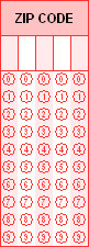
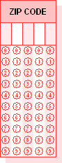
Scantron DesignExpert does not have a drop shadow tool but it is relatively easy for you to create your own simple drop shadow if you need one.
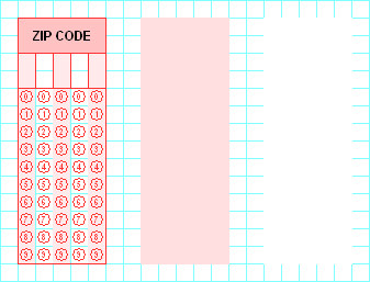
- Create or select an element.
- Draw a box of the same size as the element.
- Use Modify Box to create your "shadow" by changing the box Stroke and Fill to a screen percentage such as 15%.
- Duplicate this box and use Modify Box to change the second box Stroke and Fill to Solid Style and White Color.
- Drag the "white" box on top of your element (an OMR response grid in this case) then move it to the graphic layer behind the element (right-click the box, then choose Move to Back).
- Drag the 15% screened box on top of your element and offset down and to the right by half a response grid space. Then, move it to the graphic layer behind the element.
- Select all of the elements in your finished grid and Group them so that they stay together when moved on the workspace.
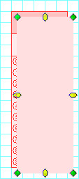
Your element is complete with drop shadow. We suggest you experiment with other shapes, screen percentages, and colors. And, be sure to add it to your Shape Library if you will use it with other form designs.