Grid Measurement dialog
This dialog appears when you click the Grid
Measurement button on
either the Graybox dialog or the Define Bar Code dialog. Use it to define
the location of graybox and software bar code grid evaluation regions
and clip regions in your application.
The title of the Grid Measurement dialog depends on
the operation you are performing:
- Create New Grid
dialog – This is the title when you do one of the following:
- Enter a new
output field, select the Graybox Tool or Bar Code Tool, and then select
the Grid Measurement button.
- Select an existing
field or grid, select the Graybox Tool or Bar Code Tool, and then select
the Grid Measurement button.
- Have no grid
selected, select the Graybox Tool or Bar Code Tool, and then select the
Grid Measurement button.
You can then enter the Grid Measurement values for
the new graybox or bar code grid.
- Modify
Grid Measurement dialog
– This is the title when you do the following:
- Select a graybox
or software bar code grid and then select, in order, the Edit Selected
Grid button and the Grid Measurement button, in the Graybox dialog or
in the Define Bar Code dialog.
- Have no grid
selected, select the Graybox Tool or Bar Code Tool, draw a grid in the
grid definition area, and then select the Grid Measurement button.
You can then modify the Grid Measurement values
for the graybox or bar code grid.
- View
Grid Measurement dialog – This is the title when you select a graybox
or software bar code grid and then select the Grid Measurement button,
in the Graybox dialog or in the Define Bar Code dialog, without first
selecting the Edit Selected Grid button. You can view the Grid Measurement
values but you cannot modify them because the graybox or bar code grid
is therefore not in edit mode.
TIP: If you are
using an imaging scanner, you may find it more convenient to draw graybox
and software bar code grid evaluation regions and clip regions directly
in the grid definition area. See Creating
a Graybox Grid and Bar Code Implementation
for additional information.
Grid Location
This is reference information. The values in this area
cannot be changed.
- Field
–shows the name of the field this graybox or software bar code
grid is appended to.
- Sheet
–shows the sheet number on which this graybox or software bar
code grid is located.
- Side
–shows the side of the sheet, Top or Bottom, on which this
graybox or software bar code grid evaluate region is located. The side
on which the clip region is located is not displayed.
Unit of Measurement
Select the measurement system used for defining the
exact coordinates for location and size of the graybox or software bar
code grid. The selection made here is used in the Evaluate Region and
Clip Region, X and Y
Region Position areas. In all cases, the origin point is the intersection
of the leading edge and
of the form.
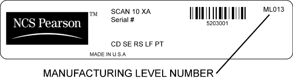
NOTE for OpScan iNSIGHT
2/4 (with Imaging) Scanner Users:
As absolute Units of Measurement (.001 in and .01 mm) is an advanced feature
of ScanTools Plus software, utilizing the full capabilities of OpScan
iNSIGHT 2/4 (with Imaging) scanners, you should ensure that your scanner
includes the advanced features in scanner Manufacturing Level ML013 or
greater.
To verify your scanner Manufacturing Level, look at the serial number label
on the back of the scanner and read the “ML” number.
If the ML number is less than ML013, call Scantron Customer Support at
800-338-5544 to arrange to have your scanner enhanced to this Manufacturing
Level.
For International users, contact your local sales representative.
Select one of the following values:
- Cell/TM
Position – Read cell and
timing mark numbers. Locations are measured to specified Cell/TM
response position centers and then clip and evaluate regions are automatically
enlarged by ScanTools to include complete OMR response positions.
- .001 in
– Thousandths of an inch. Locations are measured from the origin point
in thousandths of an inch.
- Hybrid .001 in
– A combination of read cell and timing mark numbers and thousandths of
an inch. Base locations are measured to specified Cell/TM response position
centers and then clip and evaluate regions are enlarged by the amount
you specify, defined in thousandths of an inch. When this is selected,
an additional Hybrid control, Hybrid Offset, appears in this dialog.
- .01 mm –
Hundredths of a millimeter. Locations are measured from the origin point
in hundredths of a millimeter.
- Hybrid .01 mm
– A combination of read cell and timing mark numbers and hundredths of
a millimeter. Base locations are measured to specified Cell/TM response
position centers and then clip and evaluate regions are enlarged by the
amount you specify, defined in hundredths of a millimeter. When this is
selected, an additional Hybrid control, Hybrid Offset, appears in
this dialog.
CAUTION: There
are special Unit of Measurement considerations for OpScan iNSIGHT 2/4
(with Imaging) scanners, forms without timing marks, iNAME
scan-time archiving, OMR/merge horizontal adjustment, ScanFlex, and user
exits. See information below regarding these SPECIAL
CASES.
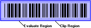
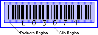
Clip and Evaluate Regions
Select the dependency of the Clip and Evaluate regions
of the graybox or software bar code. The clip region is the graphic
of the graybox or software bar code and is used for viewing in the post-scan
editor or for archiving as a separate graphic file. The evaluate region
is the area of the graybox or software bar code that is evaluated
at scan time for the presence of data. Graybox data presence is based
on the Cutoff Value defined in the Graybox dialog. Software bar code data
presence is based on decoding defined in the Define Bar Code dialog.
Clip Region Tracks
Eval Region
– the Clip Region is identical to whatever is entered in the Evaluate
Region. You cannot enter values for the Clip Region.
Clip Region is
Unique – each region is independent and can differ from the other.
This choice allows you to enter different values for the Evaluate Region
and Clip Region.
- If the Clip
Region is on the same sheet side as the Evaluate Region, you can define
the position in this dialog or you can draw the Clip Region in the grid
definition area. You can use any Unit of Measurement.
- If the Clip
Region is not on the same sheet side as the Evaluate Region, you must
draw the Clip Region in the grid definition area. You must use Cell/TM
or Hybrid Unit of Measurement.
CAUTION: If
the clip region of an ICR/OCR graybox does not fully encompass the evaluate
region,
will not be saved for that ICR/OCR graybox.
Evaluate Region
Region Position
Use these controls to define the X and Y
coordinates for two opposite corners of the evaluate region of the graybox
or software bar code. This defines the exact location and size of the
evaluate region. For the Top side of a sheet, enter X and Y
coordinate values for Upper Left and Lower Right corners. For the Bottom
side of a sheet, enter X and Y
coordinate values for the Upper Right and Lower Left corners.
X (Cell or .001"
or .01 mm) – enter the value that represents the location of the
corner of the evaluate region, along the X axis of the form. This is the
read cell number, or number of inches or millimeters from the guide edge
of the form. The unit of measure used depends on the Unit of Measurement
selected. The minimum values are 1 for Cell and 0 (zero) for .001"
or .01 mm. We recommend using minimum
values of 1 for Cell, 50 for .001", and 120 for .01 mm.
Y
(TM or .001" or .01 mm) – enter the value that represents
the location of the corner of the evaluate region, along the Y
axis of the form. This is the timing mark number, or number of inches
or millimeters from the leading edge of the form. The unit of measure
used depends on the Unit of Measurement selected. The minimum values are
1 for TM and 0 (zero) for .001" or .01 mm. We
recommend using minimum values of 1 for TM, 65 for .001", and 155
for .01 mm.
Upper Left/Upper Right – these controls refer to which
corner of the region is being defined.
Lower Right/Lower
Left – these controls refer to which corner of the region is being
defined.
CAUTION: If
a value less than the recommended minimum value is used as a value for
X or Y with .001" or .01 mm units of measurement, there is a possibility
the image will contain black (and possibly garbage) from the buffer.
Hybrid Offset
This appears only if the Unit of Measurement
selection is Hybrid .001 in or
Hybrid .01 mm. Use this to enlarge
the Evaluate Region. The base location of the region is defined by read
cell and timing mark number, measured to response position centers. You
can then enlarge the region in increments of either thousandths of an
inch or hundredths of a millimeter on both the X and Y axes.
+X (.001"
or .01 mm) – valid values are 0 – 1000 for thousandths of an inch,
and 0 – 2540 for hundredths of a millimeter.
+Y (.001"
or .01 mm) – valid values are 0 – 1000 for thousandths of an inch,
and 0 – 2540 for hundredths of a millimeter.
Upper Left/Upper Right – these controls refer to which
corner of the region is being enlarged.
Lower Right/Lower
Left – these controls refer to which corner of the region is being
enlarged.
Clip Region
Region Position
Use these controls to define the X and Y coordinates
for two opposite corners of the clip region of the graybox or software
bar code. This defines the exact location and size of the clip region.
For the Top side of a sheet, enter X and Y coordinate values for Upper
Left and Lower Right corners. For the Bottom side of a sheet, enter X
and Y coordinate values for the Upper Right and Lower Left corners. This
is not available if Clip Region Tracks Eval
Region was selected, above.
X (Cell or .001"
or .01 mm) – enter the value that represents the location of the
corner of the clip region, along the X axis of the form. This is the read
cell number, or number of inches or millimeters from the guide edge of
the form. The unit of measure used depends on the Unit of Measurement
selected. The minimum values are 1 for Cell and 0 (zero) for .001"
or .01 mm. We recommend using minimum
values of 1 for Cell, 50 for .001", and 120 for .01 mm.
Y (TM or .001"
or .01 mm) – enter the value that represents the location of the
corner of the clip region, along the Y axis of the form. This is the timing
mark number, or number of inches or millimeters from the leading edge
of the form. The unit of measure used depends on the Unit of Measurement
selected. The minimum values are 1 for TM and 0 (zero) for .001"
or .01 mm. We recommend using minimum
values of 1 for TM, 65 for .001", and 155 for .01 mm.
Upper Left/Upper
Right – these controls refer to which corner of the region is being
defined.
Lower Right/Lower Left – these controls refer to
which corner of the region is being defined.
CAUTION: If
a value less than the recommended minimum value is used as a value for
X or Y with .001" or .01 mm units of measurement, there is a possibility
the image will contain black (and possibly garbage) from the buffer.
Hybrid Offset
This appears only if the Unit of Measurement
selection is Hybrid .001 in or
Hybrid .01 mm. Use this to enlarge
the Clip Region. The base location of the region is defined by read cell
and timing mark number, measured to response position centers. You can
then enlarge the region in increments of either thousandths of an inch
or hundredths of a millimeter on both the X and Y axes.
+X (.001"
or .01 mm) – valid values are 0 – 1000 for thousandths of an inch,
and 0 – 2540 for hundredths of a millimeter.
+Y (.001"
or .01 mm) – valid values are 0 – 1000 for thousandths of an inch,
and 0 – 2540 for hundredths of a millimeter.
Upper Left/Upper Right – these controls refer to which
corner of the region is being enlarged.
Lower Right/Lower
Left – these controls refer to which corner of the region is being
enlarged.
Create Button
This button is available in the Create
New Grid dialog. Click Modify to accept the Grid Measurement settings
and close the dialog.
Modify Button
This button is available in the Modify
Grid Measurement dialog. Click Modify to accept the Grid Measurement
settings and close the dialog.
Special Cases for Units of Measurement
OpScan iNSIGHT 2/4 (with Imaging) Scanners
As absolute Units of Measurement (.001 in and .01
mm) is an advanced feature of ScanTools Plus software, utilizing the full
capabilities of OpScan iNSIGHT 2/4 (with Imaging) scanners, you should
ensure that your scanner includes the advanced features in scanner Manufacturing
Level ML013 or greater.
To verify your scanner Manufacturing Level, look
at the serial number label on the back of the scanner and read the “ML”
number.
If the ML number is less than ML013,
call Scantron Customer Support at 800-338-5544 to arrange to have your
scanner enhanced to this Manufacturing Level.
For International users, contact your local sales
representative.
Forms Without Timing Marks
If you are using forms
without timing marks, you must use an absolute Unit of Measurement
(.001 in or .01 mm) to specify Evaluate Region and Clip Region locations.
Cell/TM and Hybrid Units of Measurement cannot be used since they require
the presence of timing marks. This includes grayboxes, software bar codes,
and ICR/OCR grayboxes (if you have installed the RealTime Character Recognition
optional component).
iNAME Scan-Time Archiving
If you are using iNAME
image archiving, sparse clipping of grayboxes or software bar codes
is not compatible with use of absolute (.001 in or .01 mm) or Hybrid units
of measurement:
- If any of the
Selected Images to Archive
specified in the iNAME Configuration are for sparse clips of grayboxes
or software bar codes that use an absolute Unit of Measurement (.001 in
or .01 mm), iNAME will fail at scan time ("Problem taking clips"
error) and scanning will terminate.
- If the Selected
Image to Archive is for a sparse clip of a graybox or software bar code
that uses Hybrid Units of Measurement, iNAME will use only the Cell/TM
Position values for the clip. The Hybrid Offset values will not be used.
iNAME is compatible if the Selected Image to Archive
is for a whole sheet clip of any sheet in an application that has a graybox
or software bar code that uses an absolute (.001 in or .01 mm) or Hybrid
Units of Measurement.
OMR/Merge Horizontal Adjustment
No horizontal adjustment is made for background
form merging if you use absolute Units of Measurement (.001 in or .01
mm) for the locations of Standard Graybox, ICR/OCR Graybox, or software
bar code Evaluate Regions and Clip Regions. You must use Cell/TM Position
Units of Measurement.
ScanFlex
No horizontal adjustment is made for background
form merging if you use absolute Units of Measurement (.001 in or .01
mm) for the locations of Standard Graybox, ICR/OCR Graybox, or software
bar code Evaluate Regions and Clip Regions. You must use Cell/TM Position
Units of Measurement. To accommodate this, we recommend you:
- Use dropout
colors for lines, boxes, and text in a form area that is resolved
as a Standard Graybox, ICR/OCR Graybox, or software bar code. See ScanFlex
Form Design Rules.
- Define a larger
Evaluate Region and Clip Region to make sure the entire area is included.
User Exits
User exits
are not compatible with applications that contain grayboxes or software
bar codes that use absolute (.001 in or .01 mm) or Hybrid units of measurement:
- If the user
exit examines a graybox or software bar code absolute Unit of Measurement
(.001 in or .01 mm), it will interpret it as an invalid value.
- If the user
exit examines a graybox or software bar code Hybrid Unit of Measurement,
it will use only the Cell/TM Position values for the clip. The Hybrid
Offset values will not be used.
User exits are compatible with applications that
contain grayboxes and software bar codes that use Cell/TM Unit of Measurement
or that do not examine the graybox or software bar code Unit of Measurement
values.
 Related topics