Welcome to Scantron DesignExpert
Use Scantron DesignExpert to design, print, personalize, and program scannable forms. It puts design capabilities at your fingertips that not only enable you to create form designs, but modify them quickly and easily to meet your changing needs. You can:
- Design single- or double-sided forms, continuous forms, multi-part forms, or booklets of up to 120 pages
- Laser print your own forms on Scantron DesignExpert stock form 103188 or 265914
- Laser print forms on plain paper, with the PrintFlex option, for use with ScanTools software with the ScanFlex feature
- Personalize your forms with data from your database
- Create basic ScanTools application files and edit profiles for your form for use with Scantron scanners
- Create background form images for your form to use with ScanTools applications and Scantron image scanners
- Create merge templates to use with the MergePrint software utility
Scantron DesignExpert software provides a wide range of graphic and text capabilities, such as:
- line, box, ellipse, and polygon tools
- response grid (OMR) and hand print tools
- text tool for single line captions
- text tool for paragraphs
- text style and line spacing definition
- precise paragraph alignment
- spell checking
- rotation and zoom tools
- copy, cut, and paste functions
- color definition for lines, fill, text, and graphics
Click an element to learn about the features and link to detailed information.
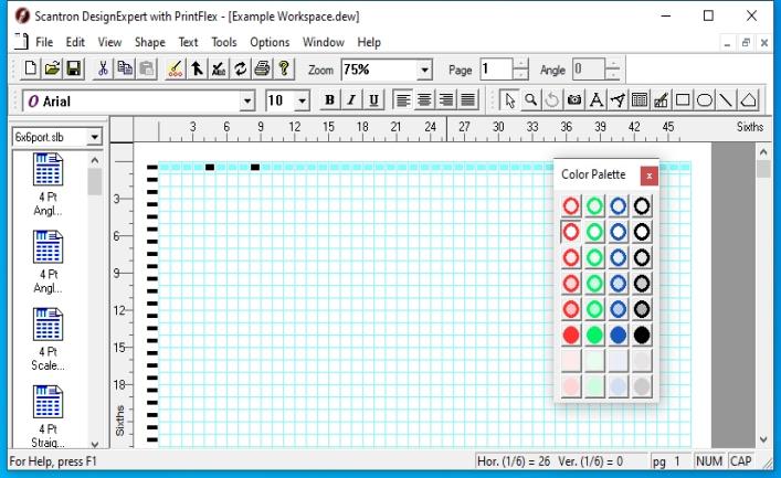
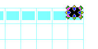
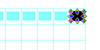
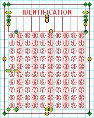
Form ID marks and timing marks are required on each page in OMR documents that will be scanned using Scantron scanners. Form ID marks are read by the scanner and uniquely identify each sheet to a scanning program. Form ID marks are black rectangles and must correspond to response positions. They are usually placed at the lead edge of the document, on the first timing mark. We recommend that each page have unique form ID marks defined.
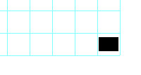
Timing marks are the small black rectangles along the guide edge of an OMR document. Each timing mark triggers the scanner to read a row of responses. We recommend that each sheet scanned have at least one timing mark. This helps identify it as a valid document, shows clearly which edge is the guide edge, and prevents a document from being fed into the scanner in the wrong manner. A timing mark is required for each row that contains a scannable response position.
You must select the appropriate form ID marks and timing marks for each page of each document. Select View > Grid Lines. This displays rectangles on the leading and guide edges of the document. A blue rectangle indicates the form ID mark or timing mark is not defined for that position; a black rectangle indicates the form ID mark or timing mark is defined.
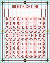
When you create a new OMR document:
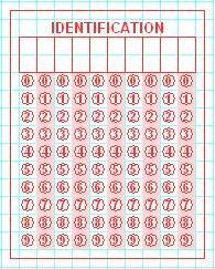
- no form ID marks are selected - all rectangles are blue
- all timing marks are selected - all rectangles are black
To select form ID marks and timing marks, simply move your mouse pointer over the appropriate rectangle and double-click with the left mouse button. Double-clicking changes the color of the rectangle. You can change the selection on and off, (black/blue) as often as needed.
The example below shows form ID marks and timing marks selected in black, the blue ones are not selected.
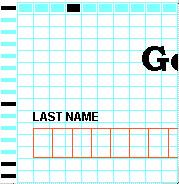
NOTE: Timing marks cannot be removed on Laser Printer forms.
TIP: You can print a Job Specification Sheet from the Job Specification Sheet dialog. This reports which form ID marks and timing marks are used on each page of the document. We recommend you print and review this before you Export to ScanTools, and before sending your document to Scantron Print Services for printing.
If you are designing a form to be printed with Scantron DesignExpert with PrintFlex, you may want to include a form ID mark on the first or last timing mark, in one of the last three response positions farthest from the timing track, so that you can use the Enable Form ID adjust… feature in ScanTools software (ScanTools Plus requires the ScanFlex option).
Form ID marks are typically placed on the first timing mark and Scantron DesignExpert enables you to double-click each mark location. This feature is not available for other locations but you can draw your own form ID mark:
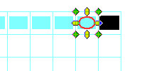
- Set Zoom to 200% so it’s easier to see your work.
- Use the Box tool to draw a box at one of the standard form ID mark positions.
- Select Modify from
the Shape menu.
- Set Stroke and Fill to 100% Black.
- Select the Position and Size tab and set Width to 0.80 and Height to 0.55. The unit of measure in both cases is 1/6".
- Click OK.
- Select Options < Snap To Grid.
- Drag your custom ID mark to overlay one of the standard form ID mark positions.
- Use the OMR Response tool to draw an OMR bubble in the location to the left-hand side of your custom form ID mark.
- Select both the OMR Response and your custom form ID mark then select Shape > Group.
- Drag the Response/Box group to the place where you want to locate the form ID mark.
- Select Shape > Ungroup then click the response bubble to deselect it.
- Select Shape > Lock to lock the custom form ID mark.
- Delete the response bubble.
The Box is reduced to the size you entered and will be off-center.
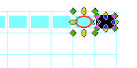
This will keep your custom form ID mark aligned to the response grid even when Snap To Grid is unchecked.
Your custom form ID mark remains selected.
Your custom form ID mark is complete.
You can use this procedure to create custom form ID marks in any OMR response location.
This form ID mark will not be included in the Job Specification Report or in your ScanTools application if you use the Export to ScanTools feature since it was not created with the standard form ID mark selection feature.
If this form ID mark is on the last timing mark and other form ID marks are on the first timing mark, then including it in your ScanTools application is optional.
For the ScanFlex feature in ScanTools software, this form ID mark must be on the first or last timing mark and in one of the last three response locations, farthest from the timing track. In addition, response position 28 is the closest position to the timing track that can be used.
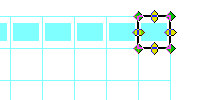
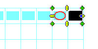
If you need to move multiple shapes that include OMR response positions, we suggest you first Group the shapes together to make sure they remain aligned to each other:
|
Multiple Shapes - Grouped |
|
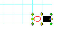
Grouped Shapes Moved Together |
|
|
|
Lines, shading, and text remain aligned to the OMR responses because they all snap to the full grid when grouped together. |
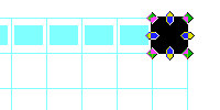
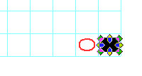
If you do not group multiple shapes before you move them, the shapes may not stay in alignment with each other.
|
Multiple Shapes - Ungrouped |
|
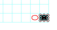
Ungrouped Shapes Moved Together |
|
|
|
Lines, shading, and text do not remain aligned to the OMR responses because they snap to the half grid while responses snap to the full grid. |

Scantron DesignExpert software allows you to rotate some shapes:
|
Shapes That Rotate |
Shapes That Cannot Rotate |
|
|
For shapes that can be rotated, the following rotation methods are available:
- Tool Bar - Angle spin box at end of tool bar. This is recommended for single shapes, not multiple shapes
- Tools menu - Rotate tool
- Tool pop-up menu - Rotate tool
- Tool Palette - Rotate tool
- Modify dialog appropriate for the shape type selected ( not all have this available for rotation). This method is recommended for rotating multiple shapes.
The following table lists the shapes that can be rotated and the methods available for rotating them:
|
Shape |
Tool Bar - Angle box |
Tools
menu |
Modify shape dialog |
|---|---|---|---|
|
Caption Text |
Yes. Baseline of all text only, NOT individual characters |
Yes. Baseline of all text only, NOT individual characters |
Modify Caption Text - Rotation and Spacing tab, baseline and text characters |
|
Graphic file in graphic box |
No |
No |
Modify Graphic - Effects tab, only in 90 degree increments |
|
Box |
Yes |
Yes |
|
|
Ellipse |
Yes |
Yes |
|
|
Line |
Yes |
Yes |
None |
|
Polygon |
Yes |
Yes |
None |
Scantron DesignExpert software allows you to import artwork from almost any illustration package. Furthermore, scanned images, such as a company or organization logo, can be imported to your form design and precisely positioned, giving you truly personalized and attractive forms.
Scantron DesignExpert software uses two types of color: dropout color and highlight (non-dropout) color. Dropout color is visible to the form user but cannot be detected by the scanner. Non-dropout color is visible to both the form user and the scanner. Effective scannable form designs make use of both color types to create forms that are easy to use and result in high data capture accuracy.
A database interface, the Merge Wizard, allows you to merge information from a database file and print it on your cut sheet forms as text, caption text, bar codes, or pre-slugged OMR response grids using your laser printer. Database file types supported are:
- Comma Separated Text - standard Windows comma delimited file that contains ASCII text with each field separated by a comma.
- Tab Delimited Text - standard Windows tab delimited file that contains ASCII text with each field separated by a TAB character.
- Microsoft Excel
- Microsoft Access
In addition, a merge text style control feature is available that allows you to add formatting tags to data in your database for font, style, color, and other text attributes.
TIP: See Merge Wizard Overview for additional information about Microsoft Excel database support, including our recommendation to convert Excel files to either comma separated or tab delimited text files.
The Export to ScanTools feature enables you to create basic ScanTools application files and edit profiles for your OMR form. You can use them with Scantron scanners as is or you can modify them with ScanTools software to add functionality such as RealTime Character Recognition, iNAME image archiving, and test scoring. The steps involved include: First, define scanning functionality for each response grid and bar code in your form. Second, set up the ScanTools output record. Third, optionally, define edits to be performed during scanning and specify program, printer, and scanner actions to be taken when edit failures occur. Finally, Export to ScanTools to create a ScanTools application file and, optionally, an edit profile.
The PrintFlex option enables you to export background form images of each page of your OMR form to use with ScanTools software.
- With Scantron image scanners, these files can be merged with scanned form images, enabling software users to see data on forms in the context of the formatted area on the form.
- Background form images can be displayed in the ScanTools Plus (version 7.0 and later) Application Module grid definition area, making it easier for the ScanTools application developer to define grids for the application.
The PrintFlex option enables you to print OMR forms on plain paper, with your own laser printer, for scanning with ScanTools software with the ScanFlex feature and a Scantron image scanner, such as the iNSIGHT 4ES. PrintFlex OMR form printing is optionally available with Scantron DesignExpert software and the MergePrint software utility.
Procedures are provided in several Help system topics. To locate them, select the Index tab in Help and then enter "Procedures." Click on Procedures in the Index to see a list of topics that contain procedures for specific tasks.
The MergePrint Utility is a standalone version of the Scantron DesignExpert merge printing software feature. It is installed automatically with Scantron DesignExpert software so that you can develop and test merge printing applications for MergePrint Utility users at distributed print locations. The MergePrint Utility can be purchased separately from Scantron for distribution to those users who don’t want or need to have full form design capability but who do need to perform their own merge printing from a database or who simply need to print "blank" forms (forms with no database merge).