Grid Definition Procedures

Grid Definition Procedures Help Topics

Copying and Pasting Grids

Grid Data Order

Grid Definition Area Procedure Summary

Multiple Grid Types and Single Fields

Grid Definition Area Procedure Summary

These procedures for working with grids in the grid definition area will help you perform common application definition tasks:

Task

Procedure

Copy and Paste a grid

  1. Click on a grid. The grid turns blue.
  2. Click Copy. The grid turns black.
  3. Click Paste. The grid will paste to the same location from which it was copied and it is pink. You can paste the grid anywhere within the same or other applications.
  4. Move the pasted grid to the desired location. While being moved, it is green.
  5. Click Append to add the grid to the selected field, or
  6. Click New to add a new field.

Cut a grid or
Cut
and Paste a grid

  1. Click on a grid. The grid turns blue.
  2. Click Cut. The grid is deleted from the grid definition area and the grid detail area. The field the grid was associated with is not cut. If desired that must be done separately.
  3. Click Paste. The grid will paste to the same location from which it was cut and it is pink. You can paste the grid anywhere within the same or other applications.
  4. Move the pasted grid to the desired location, if necessary. While being moved, it is green.
  5. Click Append to add the grid to the selected field, or
  6. Click New to add a new field.

Define a new OMR, software Bar Code, or Graybox grid

Recommended
Click+Drag method

  1. Select the OMR, Bar Code, or Graybox Tool.
  2. Click New to add a new field. Name and define the field in the Output Field Entry dialog.
  3. Select grid attributes in the OMR Tool dialog, Define Bar Code dialog, or Graybox dialog.
  4. On the grid definition area, click where you want the grid to start and while holding the mouse button down, drag the mouse pointer to where you want the grid to end and then release. For OMR grids, the direction you drag determines the data order. To Undo and redraw, click anywhere in the grid definition area.
  5. Click Append to add the new grid to the field.

Define a new OMR grid

Traditional
5-Click method

  1. Mark the appropriate bubbles on a grid for the 5-click method and place the sheet in your scanner.
  2. Click Scan Sheet. The marks you made on your grid is visible in the grid definition area.
  3. Select the OMR Tool.
  4. Click New to add a new field. Name and define the field in the Output Field Entry dialog.
  5. Select Type and Mark Style in the OMR Tool dialog.
  6. On the grid definition area, click on the marked response positions to define the OMR grid location. See Defining Grids for more information. To Undo a previous click, click Undo Grid Definition.
  7. Click Append to add the new grid to the field

De-select a grid or
De-select
a grid from multiple selected grids

  1. Alt-Click on the selected grid. The grid turns black.

Edit a grid clip region

For image scanner implementation only

  1. Select a grid. The grid turns blue.
  2. Click on Edit Selected Grid.
  3. Hold down the CTRL key.
  4. Click on any edge or corner of the clip region and drag with the mouse pointer to edit the area.
  5. Release the mouse button and the CTRL key.
  6. Click Replace to complete the edit.

Edit a software Bar Code or Graybox grid evaluate region

For image scanner implementation only

  1. Select a grid. The grid turns blue.
  2. Click on Edit Selected Grid.
  3. Click on any edge or corner of the evaluate area and drag with the mouse pointer to edit the area.
  4. Release the mouse button.
  5. Click Replace to complete the edit.

Paste a grid

  1. Cut or Copy one or more grids you want to paste elsewhere in the application.
  2. Go to the document where you want to perform the paste.
  3. Click Paste. The grid will paste to the same location from which it was copied and it is pink. You can paste the grid anywhere within the same or other applications.
  4. Move the pasted grid to the desired location. While being moved, it is green.
  5. Click Append to add the grid to the selected field, or
  6. Click New to add a new field.

Select a grid

  1. Click on a grid. The grid turns blue.

Select multiple grids

Alt-Click method

  1. Click on the first grid. The grid turns blue.
  2. Alt-Click on the second grid. The grid turns blue.
  3. Repeat Alt-Click for each additional grid.

Select multiple grids

Click+Drag method

  1. Hold down the Alt key.
  2. Click on the grid definition area and while holding the mouse button down, drag the mouse pointer through all of the grids you want to select. You do not have to include the entire grid.

Undo entire (Click+Drag) grid definition, while in process

  1. Click anywhere in the grid definition area. The entire grid is deleted so you can redraw.

Undo OMR (5-Click) grid definition while in process

  1. Click Undo Grid Definition. The most recent click is deleted so you can restart from the previous step.

Copying and Pasting Grids

Grids can be copied from anywhere within an application and pasted elsewhere within the same or a different application:

The copy set is applied using the paste button.

The default side for pasting is the current side displayed. If you want to paste to the other side of the sheet, you can switch to it using the Go To Top or Go To Bottom button. Each side must be pasted separately; you cannot paste to both sides simultaneously.

Grid Orientation Change During Copy/Paste

If you copy a grid from one side of the sheet (Top or Bottom) and paste it to the other side (Bottom or Top) and the orientation of the grid you copied is set to Left Arrow or Right Arrow, the grid orientation is automatically rotated 180 degrees.

For example, if you Copy a grid set to Left Arrow from the Top of the sheet and Paste it to the Bottom, the orientation will automatically change to Right Arrow. This automatic rotation allows the grid that you pasted to have the same orientation relative to the timing track as the grid that you copied.

If this is not the desired grid orientation, you can edit the orientation after you have added the grid to the sheet. See Edit Selected Grid in OMR Tool dialog for more information.

NOTES:

If the copied grid orientation was set to Up Arrow or Down Arrow, there is no rotation of the copied/pasted grid.

In the Grid Definition Area, the timing track is on the left side for the Top of the sheet and on the right side for the Bottom of the sheet

Graybox Copy/Paste

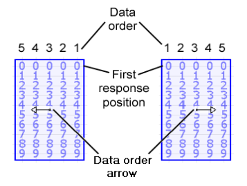
OMR Grid Data Order

This is the order of data in an OMR response grid, from the first bubble to the last bubble, relative to the output field. It is represented by an arrow in the grid, in the grid definition area.

You can define grid data order by a combination of the Orientation you select in the OMR Tool dialog and the direction you draw your OMR grid in the grid definition area.

If you edit the orientation of a grid, the grid data order may change.

Verifying Grid Data Order

You can verify grid data order in the Document Parameters section of the View Application dialog:

Multiple Grid Types and Single Fields


See Help on Help for additional information on using this help file.

See Scantron Technical Support for additional information on technical support and training options.

See the ScanTools Suite System Requirements for further details on hardware and software requirements.

ScanTools is a suite of products; the specific information you want may appear in the help for a different module. If you don't find what you're looking for here, try one of the following:


Scantron Corporation

Customer Service (forms, products, and services):

1-800-SCANTRON (722-6876)

www.scantron.com

Technical Support:

1-800-445-3141

[email protected]

Copyright © 1998-2012 Scantron Corporation. All rights reserved. Use permitted only under license. www.scantron.com. No part of the Help or user guides may be reproduced in any form, or by any means, without express permission from Scantron Corporation.

LINKS TO THIRD PARTY SITES

This help system may contain links to third party websites ("Linked Sites"). The Linked Sites are not under the control of Scantron and Scantron is not responsible for the content of any Linked Site, including without limitation any link contained in a Linked Site or any changes or modifications to a Linked Site. Scantron is not responsible for web casting or any other form of transmission received from any Linked Site. Scantron provides Users with the ability to link the Assessment System to the Linked Sites as a convenience to you, and the inclusion of any link does not imply endorsement by Scantron of the Linked Site or any association with its operators.